
Military and aerospace communication gear specifications are the environmental, electromagnetic, RF performance, encryption, and physical design requirements that equipment must satisfy before fielding on defense platforms.
This guide covers governing standards and export controls, communication system types and frequency bands, environmental and RF performance thresholds, encryption and cybersecurity mandates, and platform-specific design constraints including connectors, testing, and custom fabrication.
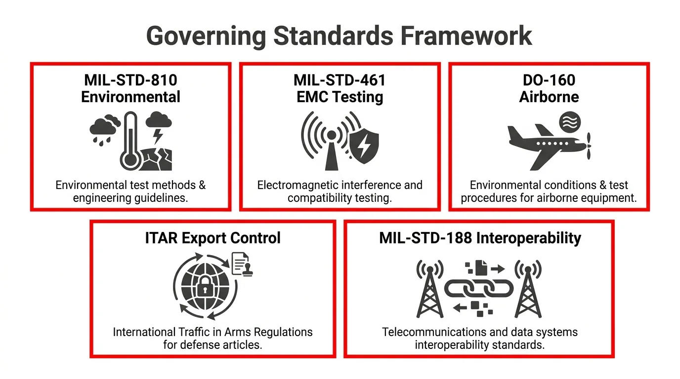
Governing standards form a layered compliance framework where MIL-STD-810 validates survivability across temperature, shock, and dust exposure; MIL-STD-461 enforces electromagnetic compatibility so devices neither emit harmful interference nor fail under external RF fields; DO-160G qualifies airborne equipment for FAA airworthiness; and MIL-STD-188 ensures telecommunications interoperability across joint and coalition networks. ITAR and EAR export controls add regulatory jurisdiction over how defense communication articles are classified and transferred.
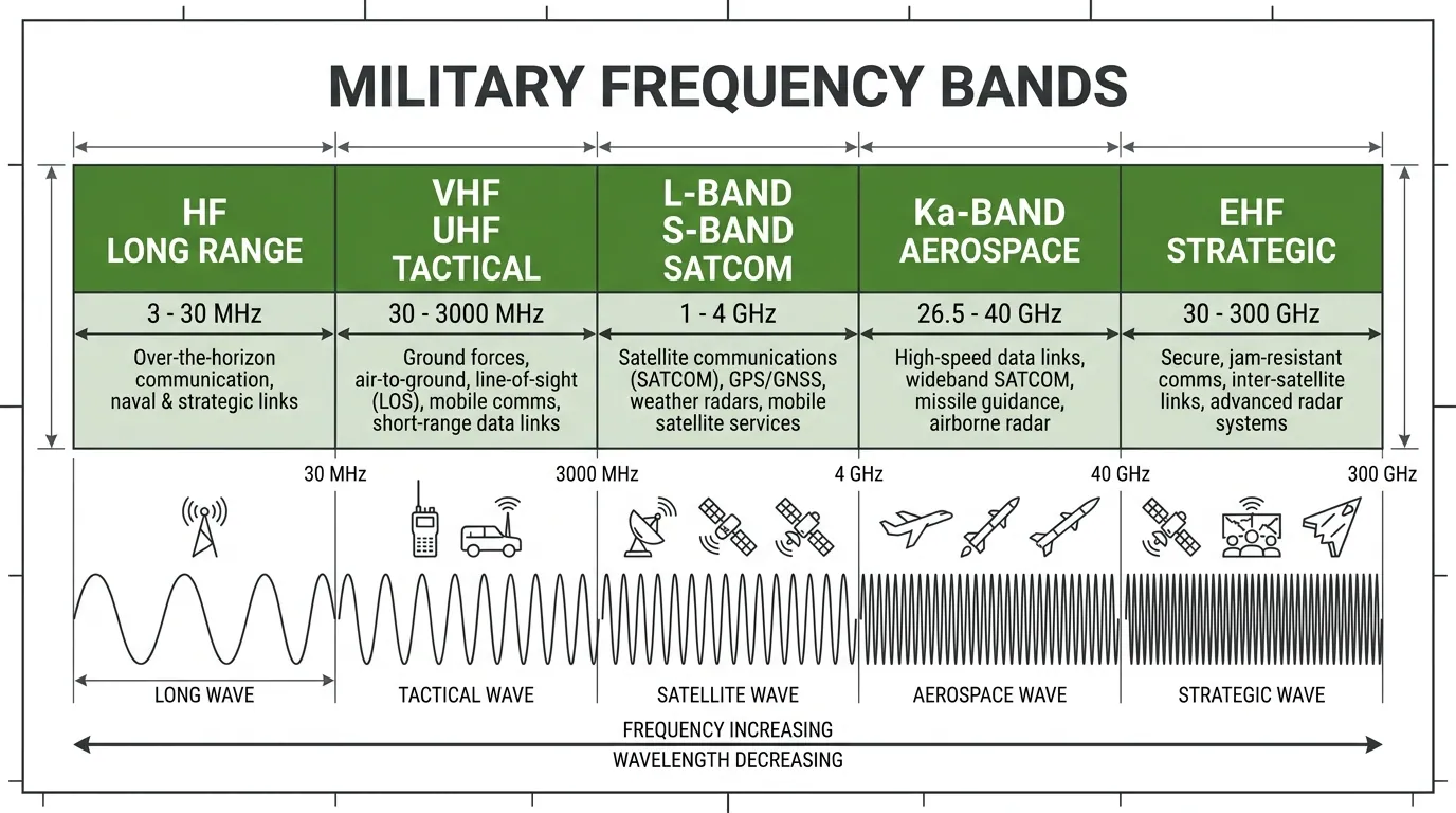
Communication system types range from manpack tactical radios and vehicle-mounted platforms to satellite terminals, airborne data links, shipboard arrays, and encrypted voice networks. Each operates across specific frequency bands, from HF ionospheric propagation for beyond-line-of-sight range through VHF/UHF tactical links, L-band and S-band satellite connectivity, Ka-band high-throughput aerospace data links, and EHF jam-resistant strategic channels.
Environmental qualification demands operation from −55°C to +70°C, shock ratings exceeding 40g, salt fog and humidity resistance, altitude performance up to 70,000 feet, and dust protection to IP67 or beyond. RF specifications define transmit power tiers, signal-to-noise thresholds, and throughput from 75 bps to 8 Mbps on protected satellite systems.
NSA Type 1 encryption certification, COMSEC key lifecycle management, and anti-jamming waveforms secure every link. SWaP constraints then dictate whether these capabilities fit a 15 kg manpack, a 19-inch vehicle rack, or a weight-critical airborne installation; and standardized MIL-DTL-38999 connectors operating from −65°C to +200°C ensure reliable integration across all platforms.
What Standards Govern Military Communication Equipment?
Military communication equipment is governed by a layered framework of environmental, electromagnetic, export control, airworthiness, and interoperability standards. The sections below cover MIL-STD-810, MIL-STD-461, ITAR and EAR export controls, DO-160, and MIL-STD-188.
What Does MIL-STD-810 Require for Communication Gear?
MIL-STD-810 requires communication gear to demonstrate survivability across a defined set of environmental stresses before fielding. The Department of Defense uses this standard to simulate real-world conditions that equipment will encounter during transport, storage, and operation.
Testing categories relevant to communication gear include:
- High and low temperature exposure, including thermal shock cycling.
- Mechanical vibration from vehicle, aircraft, and shipboard platforms.
- Mechanical shock from drops, transit, and ballistic events.
- Rain, humidity, salt fog, and fungus resistance.
- Sand and dust ingress under controlled airflow conditions.
- Low-pressure altitude simulation for airborne and high-elevation use.
Each test method prescribes specific procedures, severity levels, and pass/fail criteria tailored to the equipment’s intended operational environment. Manufacturers must document the anticipated lifecycle profile and select test tailoring accordingly, rather than simply applying every procedure uniformly.
What Does MIL-STD-461 Require for Electromagnetic Compatibility?
MIL-STD-461 requires military communication equipment to meet electromagnetic compatibility thresholds for both emissions and susceptibility. This standard ensures that devices neither radiate harmful interference nor malfunction when exposed to the electromagnetic environment of a military platform.
Key requirements include:
- Conducted emissions limits on power leads and signal lines.
- Radiated emissions limits across specified frequency ranges.
- Conducted susceptibility testing against power line transients and ripple.
- Radiated susceptibility testing to verify immunity to external RF fields.
Equipment categories, such as ground, shipboard, and airborne, each carry different limit sets and frequency ranges. For communication gear specifically, compliance is critical because uncontrolled emissions can degrade adjacent receivers, while poor susceptibility performance can render a radio unusable in a dense electromagnetic battlefield. Proper shielding, filtering, and grounding design are essential from the earliest stages of development.
What Are the ITAR and EAR Export Control Requirements?
The ITAR and EAR export control requirements are two parallel regulatory frameworks that govern how military communication equipment and related technologies may be exported from the United States. ITAR, administered by the Department of State’s Directorate of Defense Trade Controls, covers defense articles and defense services listed on the U.S. Munitions List. According to the Department of State, the President’s Export Control Reform effort is amending ITAR to revise USML Category XI, which specifically addresses military electronics.
EAR, administered by the Bureau of Industry and Security, governs dual-use items on the Commerce Control List. Encryption items fall under CCL Category 5, Part 2, covering cryptographic information security, non-cryptographic information security, and items that defeat or bypass information security. Manufacturers must determine which jurisdiction applies to their communication equipment before any transfer, technical data exchange, or foreign person access occurs. Misclassification between ITAR and EAR carries significant legal and financial penalties.
What Does DO-160 Require for Airborne Communication Systems?
DO-160 requires airborne communication systems to pass a comprehensive series of environmental qualification tests before installation on aircraft. RTCA/DO-160, formally titled Environmental Conditions and Test Procedures for Airborne Equipment, establishes standardized test methods covering temperature, altitude, vibration, power input, voltage spikes, lightning, and electromagnetic interference.
According to the Federal Aviation Administration, DO-160 versions D, E, F, and G (dated 1997, 2005, 2007, and 2010 respectively) contain acceptable environmental qualifications to demonstrate compliance with airworthiness requirements, and the FAA strongly encourages the use of RTCA/DO-160G for new articles.
Test categories most relevant to airborne communication gear include:
- Temperature and altitude combined testing.
- Vibration profiles specific to fixed-wing and rotary-wing platforms.
- Power input characteristics and voltage transient tolerance.
- Lightning-induced transient susceptibility.
- RF emissions and susceptibility across operational frequency bands.
Compliance with DO-160 is typically required alongside MIL-STD-810 and MIL-STD-461 when communication equipment operates on military aircraft.
What Role Does MIL-STD-188 Play in Interoperability?
MIL-STD-188 plays the role of defining technical performance parameters that ensure communication systems from different manufacturers, services, and allied nations can exchange information reliably. This family of standards establishes requirements for data rates, signal formats, interface protocols, and transmission quality across tactical and strategic communication networks.
Specific documents within the MIL-STD-188 series address areas such as:
- Digital voice encoding rates and compression algorithms.
- Interface standards between terminal equipment and transmission systems.
- Error correction, synchronization, and link quality metrics.
Without MIL-STD-188 compliance, a radio from one program office could fail to communicate with terminals fielded by another service branch, even when operating on the same frequency. For any program integrating communication gear across joint or coalition environments, MIL-STD-188 conformance is non-negotiable.
Understanding these governing standards establishes the compliance baseline that shapes every subsequent design decision, from frequency selection to encryption implementation.
What Are the Types of Military and Aerospace Communication Systems?
The types of military and aerospace communication systems include tactical radios, satellite terminals, airborne data links, shipboard arrays, ground-based mobile platforms, and encrypted voice and data networks.
Tactical Radio Systems
Tactical radio systems are portable, field-deployable transceivers designed for real-time voice and data exchange among ground forces. These systems operate across HF, VHF, and UHF frequency bands, enabling communication from short-range squad-level coordination to beyond-line-of-sight reach. Modern tactical radios use software-defined radio (SDR) architecture, which allows operators to reprogram waveforms and protocols without swapping hardware. Frequency-hopping spread spectrum capability is standard, providing resistance to jamming and interception. Manpack and handheld variants must meet strict SWaP constraints while maintaining MIL-STD-810 environmental ruggedness. For units operating in contested electromagnetic environments, tactical radios remain the most essential frontline communication asset.
Satellite Communication Terminals
Satellite communication terminals transmit and receive signals through orbital relay platforms, enabling global connectivity for forces beyond terrestrial network reach. According to a U.S. Government Accountability Office report, the DOD procures over 85 percent of its commercial SATCOM capability through the Commercial Satellite Communications Office, with the majority relying on geostationary orbit satellites. Terminal types range from large fixed ground stations to compact, vehicle-mounted, and man-portable units. Each terminal must support precise antenna pointing, link budget management, and wideband or narrowband operation depending on mission requirements. Protected SATCOM terminals add anti-jam and low-probability-of-intercept features for strategic communications in hostile signal environments.
Airborne Data Link Systems
Airborne data link systems are communication subsystems installed on aircraft, UAVs, and rotorcraft that exchange tactical data between platforms in real time. These systems support Link 16, Common Data Link (CDL), and Tactical Common Data Link (TCDL) protocols, enabling sensor-to-shooter connectivity and shared situational awareness. Because airborne platforms face extreme vibration, rapid pressure changes, and temperature swings, data link hardware must meet rigorous environmental qualification standards. High-bandwidth directional links allow streaming of full-motion video from ISR assets to ground stations. Low-latency performance is critical, since even millisecond delays can degrade time-sensitive targeting decisions in dynamic operational theaters.
Shipboard Communication Arrays
Shipboard communication arrays are integrated antenna and transceiver installations that provide naval vessels with multi-band voice, data, and satellite connectivity. These arrays must operate reliably in salt fog, high humidity, and constant vibration environments unique to maritime platforms. A typical surface combatant carries HF, UHF, SHF, and EHF systems simultaneously, managed through a centralized communications suite. Electromagnetic compatibility is essential aboard ships where radar, electronic warfare, and navigation systems share limited topside real estate. Conformal and whip antennas are positioned to minimize interference while maximizing coverage. For naval operations, shipboard arrays represent the only persistent link between deployed fleets and shore-based command infrastructure.
Ground-Based Mobile Communication Platforms
Ground-based mobile communication platforms are vehicle-mounted or trailer-based systems that provide deployable command, control, and communications capability in forward operating areas. These platforms integrate multiple radio systems, satellite terminals, network routers, and power generation into a single transportable package. Rapid setup and teardown times are critical, since mobile platforms must relocate frequently to avoid detection and targeting. Ruggedized shelters protect sensitive electronics from dust, extreme temperatures, and ballistic threats. Many configurations follow standardized transit case or ISO container formats for interoperability across service branches. For expeditionary forces operating without fixed infrastructure, mobile communication platforms serve as the backbone of tactical network architecture.
Encrypted Voice and Data Networks
Encrypted voice and data networks are secure communication infrastructures that protect classified information across all military domains. These networks employ NSA-certified Type 1 encryption algorithms to ensure confidentiality, integrity, and authentication of transmitted data. Encryption applies at multiple layers, covering link-level, network-level, and end-to-end protection depending on classification requirements. The U.S. Commerce Control List places encryption items under Category 5, Part 2 for Information Security, covering cryptographic systems, non-cryptographic security, and tools that defeat or bypass information security measures, according to the Bureau of Industry and Security. Key management systems distribute and rotate cryptographic keys across geographically dispersed nodes. Understanding these system types clarifies how frequency bands, environmental specs, and RF performance requirements apply across each platform.
What Frequency Bands Are Used in Military Communication Gear?
The frequency bands used in military communication gear span from HF through EHF, each serving distinct operational roles. The subsections below cover HF for long-range links, VHF and UHF for tactical operations, L-band and S-band for satellite connectivity, Ka-band for aerospace data links, and EHF for secure strategic communication.
What Is the Role of HF Band in Long-Range Military Comms?
The role of HF band in long-range military comms is to provide beyond-line-of-sight communication without reliance on satellite infrastructure. HF frequencies, spanning 3 to 30 MHz, propagate by reflecting off the ionosphere, enabling contact across thousands of kilometers. This capability makes HF indispensable for naval fleets operating in open ocean and ground forces deployed in remote areas where satellite coverage may be denied or degraded. Modern military HF radios incorporate automatic link establishment and adaptive frequency selection to maintain reliable connections despite ionospheric variability. For expeditionary units operating without fixed infrastructure, HF remains one of the most resilient communication methods available.
What Is the Role of VHF and UHF Bands in Tactical Comms?
The role of VHF and UHF bands in tactical comms is to deliver reliable, short-to-medium range voice and data links for ground, air, and naval forces in the operational area. VHF operates between 30 and 300 MHz, while UHF spans 300 MHz to 3 GHz. Both bands support line-of-sight communication, which limits range but provides low-latency, high-clarity connections essential during coordinated maneuvers. Tactical radios operating in these bands typically feature frequency-hopping spread spectrum technology to resist jamming. VHF handles most dismounted infantry and vehicle-to-vehicle links, whereas UHF supports air-to-ground coordination and shipboard systems where higher bandwidth is needed.
What Is the Role of L-Band and S-Band in Satellite Comms?
The role of L-band and S-band in satellite comms is to provide mobile, weather-resilient connectivity for military platforms requiring persistent links on the move. L-band operates between 1 and 2 GHz, and S-band spans 2 to 4 GHz. According to a 2025 U.S. Government Accountability Office report, the DOD procures over 85 percent of its commercial SATCOM capability through the Commercial Satellite Communications Office, with the majority routed through geostationary satellites. These lower frequency bands penetrate rain, foliage, and light obstructions more effectively than higher bands, making them well suited for ground vehicles, maritime vessels, and smaller terminal antennas that cannot support the dish sizes higher frequencies demand.
What Is the Role of Ka-Band in Aerospace Data Links?
The role of Ka-band in aerospace data links is to deliver high-throughput connectivity for bandwidth-intensive airborne and space-based platforms. Ka-band operates between 26.5 and 40 GHz, offering substantially wider channel bandwidths than lower frequency alternatives. This capacity supports real-time transmission of high-resolution sensor data, full-motion video, and intelligence feeds from unmanned aerial systems and reconnaissance aircraft. The trade-off is increased susceptibility to rain fade and atmospheric absorption, which requires higher transmit power and advanced adaptive coding. For missions where data volume outweighs weather resilience concerns, Ka-band consistently delivers the throughput that modern ISR operations demand.
What Is the Role of EHF in Secure Strategic Communication?
The role of EHF in secure strategic communication is to provide jam-resistant, low-probability-of-intercept links for the highest-priority military assets. EHF operates between 30 and 300 GHz, with the United States Space Force using the 44 GHz band. According to the United States Space Force, the Advanced Extremely High Frequency system provides survivable, global, secure, protected, and jam-resistant communications, delivering data rates from 75 bps to approximately 8 Mbps with 10 times the throughput of 1990s-era satellites. Narrow beamwidths at EHF frequencies make signals extremely difficult for adversaries to detect or disrupt. This makes EHF the backbone for nuclear command and control, strategic force coordination, and national leadership communications during contested operations.
Understanding which frequency bands serve each mission type directly informs the environmental and RF performance specifications that communication gear must meet.
What Environmental Specifications Must This Gear Withstand?
Military and aerospace communication gear must withstand extreme temperature ranges, mechanical shock, humidity, altitude changes, and sand or dust ingress. The following subsections detail each environmental specification category.
What Temperature Extremes Must Communication Gear Survive?
Communication gear must survive operating temperatures typically ranging from −55°C to +70°C for ground equipment, with storage ratings extending even further. Airborne and space-rated systems often face wider thermal cycling demands. According to a Defense Logistics Agency specification, military-grade connectors used in communication systems are capable of operating within a temperature range of −65°C to +200°C. These extremes reflect conditions encountered in arctic deployments, desert operations, and high-altitude flight where solar radiation intensifies thermal loads. Rapid thermal cycling between these extremes can stress solder joints, circuit boards, and housing seals, making qualified thermal endurance one of the most critical environmental parameters for any fielded communication system.
What Shock and Vibration Ratings Are Required?
The shock and vibration ratings required for military communication gear are defined primarily by MIL-STD-810 test methods. Equipment must endure high-impact mechanical shocks simulating drops, vehicle crashes, and weapons effects, often rated at 40g or higher for transit shock profiles. Vibration testing subjects gear to sustained sinusoidal and random vibration spectra replicating helicopter rotor harmonics, wheeled vehicle road inputs, and shipboard engine frequencies. For mounted systems, these profiles run continuously over hours to simulate real deployment durations. Designers reinforce internal components with shock mounts, conformal coatings, and ruggedized chassis to meet these ratings. Failing vibration qualification typically disqualifies equipment from procurement consideration entirely.
What Humidity and Salt Fog Resistance Levels Apply?
The humidity and salt fog resistance levels that apply to military communication gear address corrosion and moisture intrusion in tropical, coastal, and maritime environments. Standard humidity testing exposes equipment to high relative humidity at elevated temperatures for extended cycles. Salt fog testing, per MIL-STD-810 Method 509, subjects housings and connectors to a fine salt-laden mist that accelerates corrosion on exposed metals and degrades unsealed electronics. Shipboard communication arrays and coastal ground stations face the harshest salt fog exposure. Protective measures include anodized aluminum enclosures, nickel-plated connectors, and conformal circuit board coatings. Without verified salt fog resistance, gear deployed in naval or littoral settings risks premature failure.
What Altitude and Pressure Specifications Are Mandated?
The altitude and pressure specifications mandated for military and aerospace communication gear ensure reliable operation from sea level to above 70,000 feet. Reduced atmospheric pressure at high altitude causes dielectric breakdown risks, where electrical arcing can occur across gaps that remain safe at sea level. MIL-STD-810 Method 500 defines low-pressure testing procedures that simulate rapid ascent profiles and sustained high-altitude conditions. Airborne systems must also tolerate rapid decompression events. Sealed enclosures with pressure equalization valves protect sensitive electronics while preventing internal condensation during descent. For communication gear operating in unpressurized aircraft bays or on high-altitude UAV platforms, altitude qualification is non-negotiable.
What Sand and Dust Ingress Protection Ratings Are Needed?
The sand and dust ingress protection ratings needed for military communication gear are specified through MIL-STD-810 Method 510 and IP (Ingress Protection) ratings. Desert and arid theater deployments expose equipment to fine particulate matter that can penetrate seams, clog ventilation, and abrade optical surfaces. Most tactical communication systems require a minimum of IP67, meaning complete protection against dust ingress and low-pressure water jets. Blowing sand tests simulate wind-driven particles at velocities up to 29 m/s with particle sizes between 150 and 850 micrometers. Gasket design, sealed connector interfaces, and filtered cooling intakes are standard countermeasures. For any communication platform destined for desert or semi-arid operations, verified dust protection directly impacts mission readiness.
With environmental resilience established, RF performance specifications determine how effectively this gear communicates under those conditions.
What Are the Critical RF Performance Specifications?
The critical RF performance specifications define transmit power, receiver sensitivity, signal-to-noise ratio, and bandwidth for military and aerospace communication gear. Each parameter ensures reliable links across contested environments.
What Transmit Power Output Ranges Are Specified?
Transmit power output ranges are specified according to platform type, frequency band, and mission profile. Manpack tactical radios typically operate between 2 and 10 watts, providing sufficient range for dismounted infantry while preserving battery life. Vehicle-mounted systems scale higher, often reaching 50 watts or more to extend communication distance across rugged terrain. Airborne and shipboard platforms can require transmit power levels exceeding 100 watts to maintain links over hundreds of kilometers. Power output specifications also account for duty cycle limits, antenna gain pairing, and spectral emission masks mandated by MIL-STD-188. Selecting the correct power tier is one of the earliest decisions in any system design, since it directly constrains SWaP budgets and thermal management requirements.
What Receiver Sensitivity Thresholds Are Required?
Receiver sensitivity thresholds are required to ensure communication gear detects weak signals in high-noise operational environments. Military receivers commonly specify sensitivity levels depending on the modulation scheme and target bit error rate. Lower sensitivity values (more negative) allow detection of weaker signals at greater range or through heavier interference. Specifications often define sensitivity at a particular bit error rate, such as 10⁻⁵, ensuring consistent message integrity. Factors that influence these thresholds include:
- Noise figure of the front-end low-noise amplifier
- Channel bandwidth and modulation type
- Adjacent channel selectivity requirements
- Operating frequency band
Tighter sensitivity thresholds demand higher-quality RF front-end components, which increases both cost and design complexity.
What Signal-to-Noise Ratios Must Be Achieved?
Signal-to-noise ratios must be achieved at levels sufficient to maintain intelligible voice communication and error-free data transfer under battlefield conditions. Analog voice systems generally require a minimum SNR of 10 to 12 dB for acceptable clarity. Digital waveforms using advanced modulation, such as QPSK or 16-QAM, demand SNR values ranging from approximately 13.5 dB to approximately 18 dB depending on the data rate and coding scheme. Anti-jamming waveforms that employ spread-spectrum techniques can operate at lower apparent SNR by leveraging processing gain. Meeting these thresholds in contested electromagnetic environments remains one of the most demanding challenges in military communication gear design, making robust link budget analysis essential during qualification.
What Bandwidth and Data Throughput Rates Apply?
Bandwidth and data throughput rates apply across a wide range, from narrowband tactical voice channels to high-capacity satellite links. Tactical VHF and UHF radios often use 25 kHz channels supporting data rates from 16 kbps to 64 kbps. Wideband systems, particularly those using L-band or Ka-band frequencies, support multi-megabit throughput for video, sensor feeds, and networked operations. According to the United States Space Force, the Advanced Extremely High Frequency (AEHF) satellite communications system provides jam-resistant, secure communications with data rates spanning 75 bps to approximately 8 Mbps, delivering 10 times the throughput of its predecessor-era satellites. This breadth of throughput capability reflects the need for flexible, mission-scalable bandwidth across military platforms.
Understanding these RF benchmarks helps frame the encryption and cybersecurity layers applied on top of every link.
What Encryption and Cybersecurity Requirements Apply?
Encryption and cybersecurity requirements for military communication gear span classified-grade encryption certification, secure key distribution protocols, and electronic protection against signal interception. The subsections below cover NSA Type 1 certification, COMSEC key management, and anti-jamming specifications.
What Is NSA Type 1 Encryption Certification?
NSA Type 1 encryption certification is a designation granted by the National Security Agency to cryptographic products approved for protecting classified U.S. government information. Only devices that pass rigorous NSA evaluation earn Type 1 status, which authorizes their use across all classification levels from Confidential through Top Secret/SCI.
Type 1 certified algorithms and hardware modules are required in any communication system that transmits or receives classified data. Equipment falling under this certification is controlled as a COMSEC item and listed on the USML. According to the U.S. Department of State’s Directorate of Defense Trade Controls, military electronics, including encryption devices, are identified as defense articles subject to ITAR jurisdiction under USML Category XI.
For program managers specifying communication gear, confirming Type 1 certification early in the acquisition process prevents costly redesigns later.
What Are the COMSEC Key Management Specifications?
The COMSEC key management specifications define how cryptographic keys are generated, distributed, stored, used, and destroyed across military communication networks. These specifications fall under NSA’s Communications Security (COMSEC) doctrine, which mandates end-to-end accountability for every key throughout its lifecycle.
Key management systems must support both electronic and physical key distribution methods. Modern implementations rely on Over-the-Network Keying (OTNK) to deliver keys electronically, while legacy systems still use physical fill devices such as the AN/CYZ-10 Simple Key Loader. Encryption items used in key management fall under Category 5, Part 2 of the U.S. Commerce Control List for Information Security, as defined by the Bureau of Industry and Security.
Strict two-person integrity controls and audit logging apply at every stage, from generation through zeroization.
What Anti-Jamming and Low Probability of Intercept Specs Apply?
Anti-jamming and low probability of intercept (LPI) specifications apply to military communication systems that must maintain connectivity in contested electromagnetic environments. These specs mandate techniques such as frequency hopping, direct sequence spread spectrum, and adaptive power control to resist enemy electronic warfare.
The Advanced Extremely High Frequency (AEHF) satellite system exemplifies these requirements in practice. According to the United States Space Force, AEHF provides survivable, global, secure, protected, and jam-resistant communications for high-priority military ground, sea, and air assets, with data rates ranging from 75 bps to approximately 8 Mbps.
LPI waveforms reduce the spectral signature of transmissions, making detection by hostile signals intelligence significantly harder. Combined with anti-jam capabilities, these specifications ensure operational communication continuity even under active electronic attack.
Understanding these cybersecurity layers helps frame the physical design trade-offs that SWaP constraints impose on communication hardware.
What Size Weight and Power Constraints Shape Design?
Size, weight, and power (SWaP) constraints shape design by dictating the physical footprint, mass budget, and energy consumption allowable for each platform type. The subsections below cover how SWaP requirements differ across manpack, vehicle-mounted, and airborne systems.
How Do SWaP Requirements Differ for Manpack Systems?
SWaP requirements for manpack systems differ by imposing the most aggressive limits across all three dimensions, since a single operator must carry, power, and operate the equipment on foot. Total system weight, including radio, battery, antenna, and accessories, typically cannot exceed approximately 15 kilograms for extended dismounted patrols. Power consumption must remain low enough for battery operation over 8- to 12-hour missions without resupply. These constraints force designers to prioritize compact, energy-efficient architectures that sacrifice some transmit power and data throughput in exchange for portability. In practice, manpack radios balance operational range against the physical endurance limits of the warfighter carrying them.
How Do SWaP Requirements Differ for Vehicle-Mounted Systems?
SWaP requirements for vehicle-mounted systems differ by relaxing weight limits while introducing strict volumetric and power-draw constraints tied to platform electrical architecture. Tactical ground vehicles and aircraft provide 28 VDC and 270 VDC power buses, respectively, but total available wattage is shared among communications, electronic warfare, and C2 systems. Equipment must fit standardized rack configurations, often 19-inch RETMA racks or custom shock-isolated enclosures, within confined crew compartments. Weight distribution matters for vehicle center-of-gravity calculations, particularly when roof-mounted antennas add mass above the chassis. Vehicle-mounted communication suites can therefore support higher transmit power, wider bandwidth, and multi-channel operation compared to manpack variants, provided the installation respects platform integration limits.
How Do SWaP Requirements Differ for Airborne Platforms?
SWaP requirements for airborne platforms differ by imposing the strictest power-to-weight ratios, because every kilogram directly affects fuel consumption, payload capacity, and flight performance. Airborne communication gear must meet rigorous vibration, altitude, and thermal cycling profiles simultaneously. Power budgets are tightly allocated across avionics subsystems, leaving limited headroom for communications equipment. Cooling is another critical factor; convection-cooled designs common in ground systems often give way to forced-air or liquid-cooled architectures at altitude. These combined constraints drive airborne communication systems toward highly integrated, multi-function designs that consolidate radio, datalink, and SATCOM into shared processing hardware wherever possible.
With platform-specific SWaP budgets defined, connector and interface standards ensure these systems integrate reliably across installations.
What Connector and Interface Standards Are Specified?
The connector and interface standards specified for military and aerospace communication gear define the physical, electrical, and environmental requirements that ensure reliable signal transmission in harsh operational conditions.
Military communication systems rely on standardized connector families governed by defense specifications. According to the Defense Logistics Agency ASSIST-QuickSearch database, the primary specification covers four series of miniature, high-density, circular, environment-resistant electrical connectors with removable crimp contacts, or hermetically sealed electrical connectors with fixed, nonremovable contacts. Both environment-resistant and hermetically sealed variants are available with bayonet, threaded, or breech-coupled mating systems, and these connectors operate within a temperature range of -65°C to +200°C.
Key connector and interface standards used across military communication platforms include:
- MIL-DTL-38999 specifies high-density circular connectors for aerospace and defense electronics, supporting signal, power, and fiber-optic contacts.
- MIL-DTL-26482 covers miniature circular connectors commonly used in ground-based and vehicular communication systems.
- MIL-STD-1553 defines a serial data bus interface standard for avionics and platform-level communication between subsystems.
- MIL-STD-1760 governs the electrical interface between aircraft and stores, including communication-capable munitions and pods.
- Fiber-optic interfaces following MIL-PRF-29504 support high-bandwidth, EMI-resistant data links in shipboard and airborne arrays.
Standardized connectors matter beyond simple physical compatibility. When a communication system must operate across joint service environments, from a manpack radio to a vehicle-mounted terminal to an airborne data link, consistent interface specifications prevent integration failures that could compromise mission-critical connectivity. Selecting the right coupling mechanism, whether bayonet for quick-disconnect tactical use or threaded for vibration-resistant airborne installations, directly affects system reliability under operational stress.
Understanding these interface standards is essential before qualifying communication gear through formal testing and certification processes.
What Testing and Qualification Processes Validate Compliance?
Testing and qualification processes validate compliance by subjecting military and aerospace communication gear to structured environmental, electromagnetic, and functional evaluations against governing standards. Key processes include environmental stress screening, EMI/EMC testing, and formal qualification testing.
Environmental Stress Screening and Qualification Testing
Environmental stress screening subjects communication equipment to accelerated temperature cycling, vibration, humidity, and altitude conditions that replicate operational extremes. Qualification testing goes further by executing the full test matrix defined in standards such as MIL-STD-810 and RTCA/DO-160. According to an FAA advisory circular, the FAA strongly encourages the use of RTCA/DO-160G for new articles, recognizing versions D through G as containing acceptable environmental qualifications to demonstrate compliance with airworthiness requirements. Equipment that passes every test category within the applicable standard earns formal qualification status, which is a prerequisite for fielding in military or certified airborne platforms.
EMI and EMC Compliance Testing Under MIL-STD-461
EMI and EMC compliance testing under MIL-STD-461 verifies that communication gear neither emits harmful electromagnetic interference nor suffers degraded performance when exposed to external emissions. Test procedures measure conducted and radiated emissions across defined frequency ranges, along with susceptibility thresholds for both conducted and radiated interference. Failing any single emissions or susceptibility test category can disqualify equipment from integration into defense platforms. Given how densely packed modern military vehicles and aircraft are with electronics, passing MIL-STD-461 is arguably the most operationally consequential gate in the entire qualification process.
First Article Testing and Production Lot Acceptance
First article testing confirms that an initial production unit meets all design, performance, and material specifications before full-rate production begins. The process typically includes dimensional inspection, functional performance verification, and environmental qualification of the representative sample. Production lot acceptance testing then applies sampling-based inspections to each manufacturing lot, checking critical parameters such as connector integrity, RF output power, and encryption module function. These sequential gates ensure that compliance demonstrated during qualification carries through to every delivered unit, not just the prototype.
Understanding qualification rigor clarifies why custom fabrication partners must align manufacturing precision with stringent defense standards.
How Does Custom Fabrication Support Military Communication Gear?
Custom fabrication supports military communication gear by translating strict specifications into purpose-built enclosures, platforms, and integrated systems. The subsections below cover Craftsmen Industries’ capabilities and the key takeaways from this guide.
Can Craftsmen Industries Build Custom Military Communication Enclosures and Mobile Platforms?
Yes, Craftsmen Industries can build custom military communication enclosures and mobile platforms. Operating from a 127,000 sq. ft. vertically integrated facility near St. Louis County, Missouri, Craftsmen Industries provides in-house design, engineering, fabrication, and installation for military and aerospace applications. This end-to-end control allows each enclosure or mobile platform to be tailored to specific communication system requirements, including environmental protection, EMI shielding provisions, and precise connector integration. Government agencies and military organizations rely on Craftsmen Industries for specialized builds such as mobile command centers and custom equipment housings. With over 40 years of fabrication experience, Craftsmen Industries delivers assets on time while maintaining the quality standards defense programs demand.
What Are the Key Takeaways About Military and Aerospace Communication Gear Specifications?
The key takeaways about military and aerospace communication gear specifications center on several interconnected requirements:
- MIL-STD-810, MIL-STD-461, and DO-160G establish the environmental and electromagnetic baselines every system must meet.
- ITAR and EAR export controls govern how defense communication articles are classified, handled, and transferred.
- Frequency band selection, from HF through EHF, determines range, throughput, and anti-jam resilience for each mission profile.
- SWaP constraints shape whether a system fits a manpack, vehicle mount, or airborne platform.
- NSA Type 1 encryption and COMSEC key management ensure end-to-end information security.
Meeting these specifications requires close coordination between system designers and fabrication partners. Choosing a fabricator with vertically integrated capabilities reduces handoff delays and keeps compliance traceable from initial design through final qualification testing.
Filter Posts by Tag
related posts

Optimize performance and durability in mobile command centers with smart material choices. Balance strength, weight, and protection for mission-ready efficiency.

Enhance emergency response with advanced Mobile Command Centers engineered for rapid deployment, real-time coordination, and mission-critical control.

Optimize field operations with custom storage in mobile command units, keeping equipment secure,organized, and mission ready for faster, safer deployments.
