
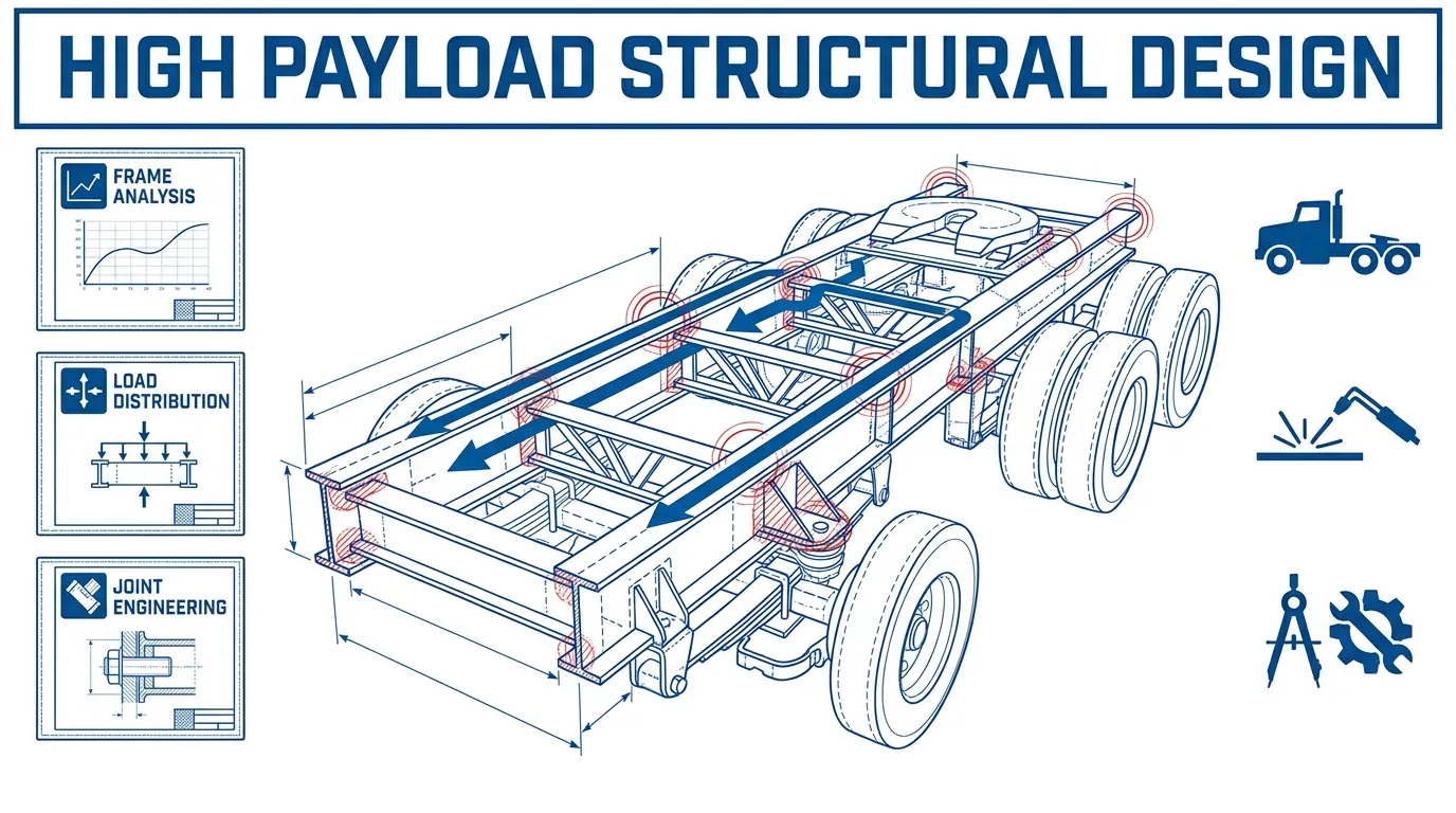
Structural design for high payload mobile units is the engineering discipline that sizes frames, chassis, floors, and connections to safely carry heavy operational loads through every phase of transit, deployment, and service life.
This guide covers load requirements and material selection, chassis configuration and structural analysis, weight distribution and joint engineering, floor system design and fatigue durability, regulatory compliance and environmental exposure, common failure modes, and vertically integrated fabrication.
Defining the complete load envelope is the starting point for every structural decision. Static dead loads, dynamic transit forces, live occupant and equipment loads, and the distinction between distributed and concentrated floor loads each impose different demands on the frame, and mischaracterizing any single category can cascade into undersized members or unsafe deflection.
Material selection balances strength-to-weight ratio, fatigue resistance, corrosion behavior, and cost across high-strength steel, aluminum alloys like 6061-T6 and 7075-T651, fiber-reinforced polymers, and hybrid combinations that can reduce component weight by 10% to 60% depending on application.
Chassis configuration, from single-axle to tandem, tri-axle, and multi-axle platforms, sets the gross vehicle weight rating and usable payload envelope. Structural analysis methods including finite element analysis, fatigue and cyclic stress evaluation, and modal vibration testing validate that each configuration performs under real service loads.
Weight distribution, center-of-gravity placement, and cargo securement directly govern rollover stability and axle-specific compliance. Joint and connection strategies at welded, bolted, and subframe interfaces determine whether the load path survives millions of fatigue cycles or cracks prematurely.
Floor system engineering, vibration durability, safety codes spanning FMVSS, DOT, ASCE, and AISC, environmental threats from thermal cycling to chloride corrosion, and documented failure modes round out the structural picture. Vertically integrated fabrication, as practiced by Craftsmen Industries, unifies these disciplines under one workflow so engineering intent transfers directly into built reality.
Why Does Structural Integrity Matter in High Payload Mobile Units?
Structural integrity matters in high payload mobile units because it determines whether the chassis, frame, and body can safely support operational loads throughout the unit’s entire service life. Without it, load paths fail, components deform, and catastrophic collapse becomes possible. The sections below define structural integrity in this context, explain how payload stresses chassis systems, and outline what happens when a load path is compromised.
What Is Structural Integrity in a Mobile Unit?
Structural integrity in a mobile unit is the ability of every load-carrying component to operate at its designed performance level under the full pressure of payload, self-weight, and external forces. According to Brunel University London, structural integrity is important “not only when something is being built, but also throughout its life cycle.” In mobile applications, this means the frame, chassis, floor system, and all connections must resist static dead loads while parked, dynamic forces during transit, and live loads during deployment. A unit with sound structural integrity redistributes stress through continuous load paths, preserves stability under braking and cornering, and resists degradation from fatigue or corrosion over thousands of road miles.
Why Does Payload Affect Chassis Integrity?
Payload affects chassis integrity because every kilogram of cargo generates forces that the frame rails, crossmembers, and axle assemblies must absorb without exceeding their ultimate limit state. Higher payloads amplify bending moments along the frame, increase shear at bolted and welded connections, and raise the center of gravity, which reduces rollover stability. When gross vehicle weight rating limits are approached or exceeded, margins against failure narrow significantly. Fatigue damage also accelerates under heavier cyclic loading, shortening service life at stress concentration points. For high payload mobile units, chassis integrity depends on matching axle capacity, frame section modulus, and connection strength to the actual operational load envelope.
What Happens When a Load Path Fails?
A load path failure occurs when one or more structural elements can no longer transfer forces to adjacent members, triggering progressive overload across the remaining structure. NHTSA established FMVSS No. 227 specifically to enhance rollover structural integrity and reduce ejection risk for buses with a GVWR greater than 11,793 kg (26,000 lb), recognizing that structural failure in heavy vehicles carries severe consequences. In a high payload mobile unit, a failed load path can manifest as frame cracking at a weld toe, floor panel separation from the chassis, or subframe bolt shear. Each of these redistributes stress to components not designed to carry it, creating a cascade that compromises the entire structure.
Understanding why structural integrity is foundational sets the stage for defining the specific load requirements every high payload mobile unit must satisfy.
What Are the Key Load Requirements for High Payload Mobile Units?
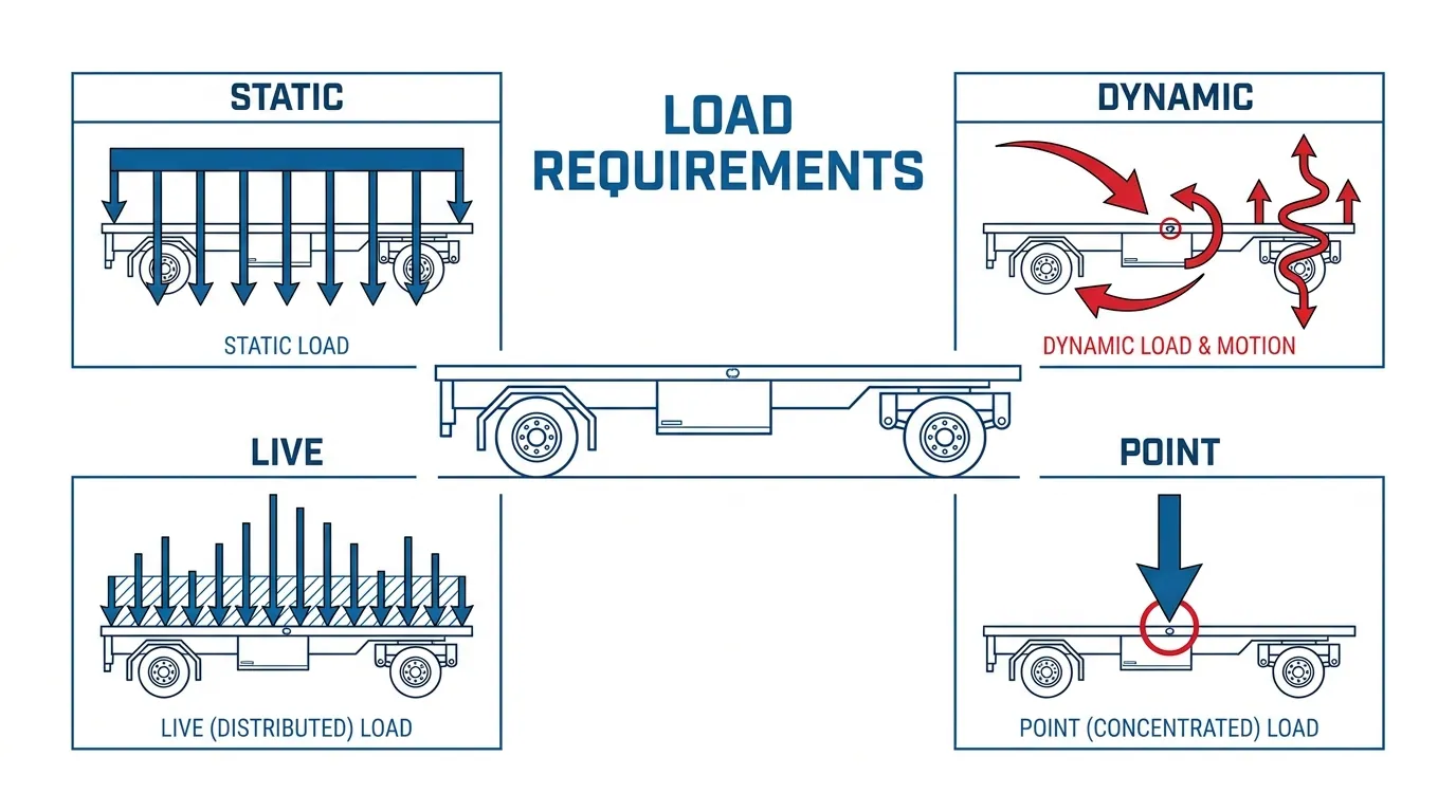
The key load requirements for high payload mobile units include static, dynamic, live, distributed, and point loads. Each category defines how forces act on the frame, floor, and chassis during storage, transit, and operational use.
What Are the Static Load Requirements for Mobile Unit Frames?
The static load requirements for mobile unit frames define the permanent and imposed forces the structure must support at rest. Dead loads include the frame’s own weight, while imposed loads account for fixed equipment, interior buildout, and stored payload. These forces act per unit length, area, or volume across the chassis and produce reaction forces at each support point.
According to GOV.UK, maximum authorised mass (MAM) represents the weight of a vehicle or trailer including the maximum load that can be carried safely on the road, with gross combination weight (GCW) covering the tractor unit plus trailer plus load. Static load cases should identify bounding loads that maintain structural integrity under all stationary conditions. For high payload mobile units, physical-test correlation with static FEA results is essential, since analytical models alone can carry significant uncertainty without measured validation.
What Are the Dynamic Load Requirements During Transit?
The dynamic load requirements during transit account for forces that amplify, shift, or fluctuate as the vehicle moves. Braking generates longitudinal deceleration loads, cornering introduces lateral acceleration, and road irregularities produce vertical impact forces. Payload that shifts during braking can overload an axle and reduce steering-axle load, compounding the dynamic stress on the frame.
According to NASA’s Johnson Space Center Standard JSC-65829 Revision B, the load requirements “represent the minimum set of conditions necessary to ensure proper identification of bounding loads and loading conditions” that maintain structural integrity across all phases of the hardware life cycle. Dynamic models validated against physical test data are critical, because road-induced stress histories accumulate fatigue damage and can initiate cracks at stress concentrations over time.
What Are the Live Load Requirements for Occupant and Equipment Use?
The live load requirements for occupant and equipment use address transient forces from people, movable equipment, and impact events inside a deployed mobile unit. The floor assembly must resist uniformly distributed loads, concentrated loads from heavy equipment legs, and impact loads from dropped items, all while maintaining serviceability and staying within allowable stress limits.
According to the National Bureau of Standards, the traditional deflection criterion requires that a horizontal member not deflect more than 1/360 of the span under a prescribed live load. For payload-rated mobile floors, separating strength checks from serviceability checks is essential; a floor can meet strength requirements yet still feel unacceptably bouncy or allow equipment to shift if deflection limits are ignored.
What Are the Distributed vs Point Load Considerations?
The distributed vs point load considerations determine how forces are modeled and where structural reinforcement is needed. A distributed force spreads across an area of the payload-rated floor, while a concentrated load acts at a single point, such as an equipment leg or jack stand.
According to Penn State University’s Mechanics Map, the equivalent point load is a single point force that is statically equivalent to the original distributed force, causing the same reaction forces on a constrained body or the same accelerations on a free body. Converting between these load types matters in design-to load analysis, because a uniform load may be safe overall yet create localized overstress when concentrated at one location. Floor stiffness and load continuity between the structural deck and chassis must account for both scenarios.
Understanding these load categories establishes the foundation for selecting appropriate materials and chassis configurations.
What Materials Are Used in High Payload Mobile Unit Structures?
The materials used in high payload mobile unit structures include high-strength steel, aluminum alloys, advanced composites, and hybrid combinations. Each material offers distinct trade-offs in strength-to-weight ratio, fatigue resistance, and cost.
High-Strength Steel
High-strength steel is the most common structural material in high payload mobile unit frames. Advanced high-strength steel (AHSS) and high-strength low-alloy (HSLA) grades deliver high yield strength, excellent weldability, and proven fatigue performance at a lower cost per pound than aluminum or composites. AHSS resists permanent deformation under heavy concentrated loads, making it well suited for chassis rails, crossmembers, and subframe mounting points. Steel’s predictable behavior under cyclic stress simplifies fatigue analysis and weld qualification to standards like AWS D1.5. For most payload-critical mobile structures, steel remains the baseline against which lighter alternatives must justify their added cost and complexity.
Aluminum Alloys
Aluminum alloys reduce structural weight while maintaining adequate strength for many mobile unit components. The two most widely used grades are 6061-T6 and 7075-T651, each offering different balances of formability, corrosion resistance, and fatigue life. According to fatigue research archived by the University of Alabama Libraries, strain-controlled fatigue tests on 6061-T6 and 7075-T651 characterized the fatigue behavior of both alloys, including specimens exposed to elevated temperatures, using traditional strain-life analysis. Aluminum 7075-T651 provides higher tensile strength but lower corrosion resistance than 6061-T6, so material selection depends on the operating environment. Designers typically reserve aluminum for upper body panels, flooring supports, and secondary structures where weight savings directly increase usable payload.
Advanced Composites and Fiber-Reinforced Polymers
Advanced composites and fiber-reinforced polymers (FRPs) offer the highest specific strength among structural materials for mobile units. Glass fiber-reinforced polymer (GFRP) and carbon fiber-reinforced polymer (CFRP) resist corrosion, reduce weight significantly, and can be molded into complex geometries. According to the U.S. Department of Energy’s Transportation Technologies Office, replacing heavy steel components with materials such as high-strength steel, aluminum, or glass fiber-reinforced polymer composites can decrease component weight by 10% to 60%. However, FRP fatigue properties vary significantly based on fiber type, resin selection, and manufacturing process. Delamination remains the primary failure mode, requiring careful inspection protocols that differ from metal structures.
Hybrid Material Combinations
Hybrid material combinations pair two or more materials to optimize strength, weight, and cost across different zones of a mobile unit structure. A common approach uses steel for the primary chassis frame and load path, aluminum for secondary framing and body panels, and GFRP or CFRP for non-structural enclosures or aerodynamic components. Fiber-metal laminates bond thin aluminum sheets with composite layers to achieve damage tolerance superior to either material alone. These combinations let engineers place high-strength, heavy material only where load demands require it, while lighter materials handle lower-stress areas. Successful hybrid designs depend on joint compatibility, since dissimilar materials introduce galvanic corrosion risk and differential thermal expansion at connection points.
With materials selected for each structural zone, chassis configuration determines how those materials translate into usable payload capacity.
How Does Chassis Selection Affect Structural Design?
Chassis selection affects structural design by determining the axle configuration, gross vehicle weight rating, and usable payload envelope of every high-payload mobile unit. The subsections below cover single-axle, tandem-axle, tri-axle/multi-axle configurations, and the distinction between commercial truck and trailer chassis platforms.
How Does a Single-Axle Chassis Affect Payload Capacity?
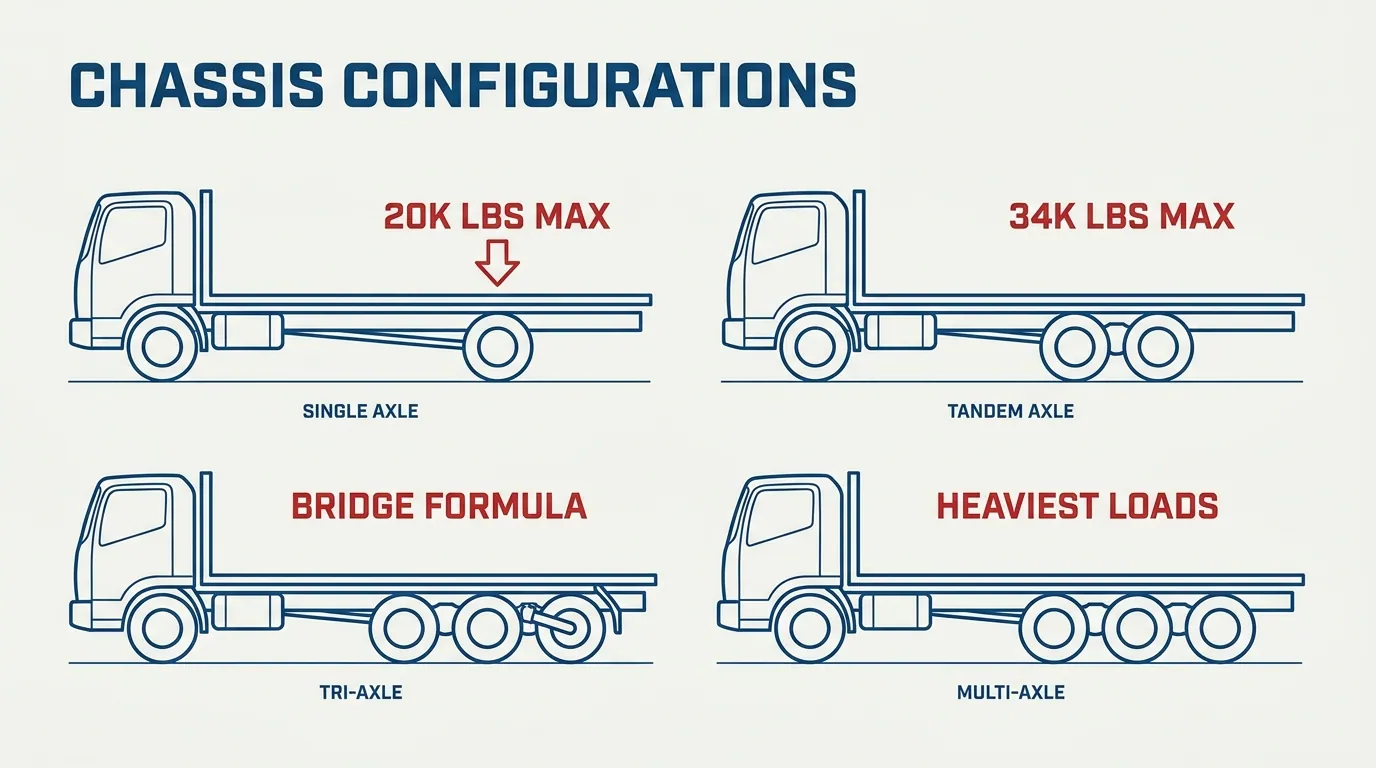
A single-axle chassis affects payload capacity by limiting gross weight to one axle’s rated load. Under 23 CFR 658.17, the maximum gross weight on any single axle is 20,000 pounds. After subtracting tare weight for the frame, cab, and body, usable payload on a single-axle platform is relatively modest. According to the Federal Highway Administration, vehicles are defined by the number of axles in contact with the road, and floating axles count only when in the down position. This classification directly shapes how engineers size frame rails, crossmembers, and suspension mounts. For lighter mobile units that stay well below 20,000 pounds gross, a single-axle chassis keeps tare weight low and simplifies structural packaging.
How Does a Tandem-Axle Chassis Affect Payload Capacity?
A tandem-axle chassis affects payload capacity by distributing gross weight across two closely spaced axles. Federal regulation under 23 CFR 658.17 caps tandem-axle gross weight at 34,000 pounds. The additional axle spreads bending loads across a longer section of frame, reducing peak stress at any single crossmember. Structurally, tandem configurations require careful attention to axle spacing, suspension equalization, and load-path continuity between the body and chassis. For most high-payload mobile units, the tandem-axle platform offers the strongest balance between legal payload envelope and frame complexity.
How Does a Tri-Axle or Multi-Axle Chassis Affect Payload Capacity?
A tri-axle or multi-axle chassis affects payload capacity by adding axle groups (tridem or quad configurations) that raise the allowable gross weight under the Federal Bridge Formula. More axles distribute concentrated loads over additional ground-contact points, which reduces per-axle stress and satisfies bridge-span weight limits for heavier units. Lift axles, when deployed, count toward the vehicle’s axle classification; when raised, they do not. This flexibility lets operators adjust load distribution for varying payload conditions. Structurally, each additional axle introduces more mounting points, suspension brackets, and load-transfer interfaces that must be integrated into the frame without creating stress concentrations. Multi-axle platforms suit the heaviest mobile units where payload demand exceeds tandem-axle limits.
How Does a Commercial Truck Chassis Differ From a Trailer Chassis?
A commercial truck chassis differs from a trailer chassis in structural configuration, load-path design, and regulatory classification. A rigid truck (straight truck) carries its payload on a single unified frame that also houses the engine, drivetrain, and cab. A semitrailer chassis, by contrast, transfers front-end loads through a fifth-wheel coupling to a separate tractor, creating an articulated vehicle with distinct load paths at the kingpin and rear axle group. According to the U.S. Department of Energy, Office of Scientific and Technical Information, Huck-bolting is a common joining method in heavy truck chassis structures, and benchmark testing evaluated the static and fatigue behavior of steel-to-steel chassis joints at the single Huck-bolt level. This distinction in joint loading is critical: rigid truck frames must resist full bending along their entire length, while semitrailer frames concentrate stress near the gooseneck and rear suspension mounts. Choosing between a truck chassis and a trailer chassis shapes every downstream structural decision, from crossmember spacing to floor-to-chassis load transfer.
Understanding how each chassis type distributes loads sets the foundation for the structural analysis methods covered next.
What Structural Analysis Methods Apply to Mobile Unit Design?
The structural analysis methods that apply to mobile unit design include finite element analysis, fatigue and cyclic stress analysis, and modal and vibration analysis. Each method evaluates a different aspect of structural performance under real-world loading.
Finite Element Analysis
Finite element analysis (FEA) predicts how a mobile unit’s structure responds to static, thermal, and dynamic loads by dividing the geometry into discrete elements and solving for stress, strain, and deflection at each node. According to a NASA Technical Reports Server publication, FEA is regularly used during the engineering cycle of mechanical systems, and the finite element model is often correlated with physical test results to determine the validity of analytical results. For high-payload mobile units, correlation between the computational model and measured service data is essential; without it, predicted safety margins remain unverified. The AISC Specification further supports this analytical framework by incorporating both LRFD and ASD design methods for structural steel, giving engineers standardized criteria against which FEA outputs can be checked.
Fatigue and Cyclic Stress Analysis
Fatigue and cyclic stress analysis evaluates how repeated loading and unloading degrades structural elements over time. As Pu Huang, Yunxiang Yin, Daniel McNaulty, and Wenyi Yan note in Engineering Failure Analysis (via Monash University Research Repository), cracks will initiate and subsequently grow until the structure fractures under cyclic loading, a phenomenon commonly seen in heavy-duty trailers. Engineers use S-N curves and Miner’s Rule to estimate cumulative fatigue damage from variable-amplitude stress histories. Critically, fatigue life depends not on the basic strength of a member but on the actual stresses at discrete points such as attachments or abrupt section changes. Stress concentrations at weld toes, bolt holes, and gusset transitions deserve the closest scrutiny during this analysis phase. Ignoring road-induced cyclic stress is, in practice, the fastest path to premature frame cracking on high-payload platforms.
Modal and Vibration Analysis
Modal and vibration analysis identifies the natural frequencies and mode shapes of a mobile unit’s structure so engineers can prevent resonance under road-induced excitation. Experimental modal testing measures how a physical prototype vibrates, while a finite element model predicts mode shapes computationally. Cross-orthogonality checks compare test and model results to validate accuracy. Road surfaces produce complex, often non-Gaussian excitation from bumps and potholes that traditional random-vibration test signals may not capture accurately. When a payload’s operating frequency overlaps a structural natural frequency, dynamic amplification can multiply stresses well beyond static predictions. Identifying and separating these frequencies early in design protects joints, fasteners, and floor systems from accelerated fatigue damage throughout the unit’s service life.
With analysis methods validated, the next step is understanding how weight distribution influences structural performance.
How Does Weight Distribution Influence Structural Performance?
Weight distribution influences structural performance by determining how payload forces transfer through the chassis, across axle groups, and into the road surface. The subsections below cover center of gravity placement, axle load balancing, and payload shifting risks.
How Does Center of Gravity Placement Affect Stability?
Center of gravity placement affects stability by dictating how vertical and lateral forces distribute across a mobile unit’s axle groups. A high or off-center center of gravity reduces the rollover threshold, while forward or rearward bias overloads individual axles even when total GVWR remains compliant.
As reported in a 2023 study published in Scientific Reports, researchers František Synák, Alexandra Smolková, and Klára Žúžiová found that “the position of the vehicle’s centre of gravity has an impact on its driving performances, and it also affects the vehicle’s impact on its surroundings.”
For high-payload mobile units, this means that cargo tank configurations and trailer frame designs with elevated equipment are especially vulnerable. When the center of gravity shifts during braking or cornering, the resulting force transfer can exceed the steering axle’s rated capacity, compromising both handling and structural integrity.
How Does Axle Load Balancing Prevent Structural Failure?
Axle load balancing prevents structural failure by distributing payload forces proportionally across each axle group, keeping individual axle loads within GAWR limits while the total remains under GVWR. Without proper balance, localized overload pushes load-carrying elements past their ultimate limit state.
According to the United Nations Office for Disaster Risk Reduction, “structural failure corresponds to the exceedance of ultimate limit state in many of the load-carrying elements, which compromise the structural stability” of a structure. Although this definition applies broadly, the principle transfers directly to mobile unit superstructures where uneven axle loading concentrates stress in specific frame sections.
Key factors that affect axle-load distribution include:
- Axle spacing and count, which determine how the Federal Bridge Formula allocates permissible weight.
- Payload position relative to the kingpin or rear axle group.
- Whether floating or lift axles are deployed, since axle count changes classification and load limits.
Overlooking axle-specific compliance is one of the most common design errors in high-payload mobile units; total weight can be legal while a single axle group silently exceeds its rated capacity.
How Does Payload Shifting During Transport Create Risk?
Payload shifting during transport creates risk by relocating the center of gravity mid-transit, generating unplanned lateral and longitudinal forces that the chassis and cargo securement system must absorb. Unsecured or poorly restrained loads can slide during braking, lane changes, or curve negotiation, raising rollover probability and accelerating fatigue cracking in the trailer frame.
FMCSA requires that cargo securement systems withstand the following deceleration and acceleration forces, applied separately:
- 0.8 g deceleration in the forward direction
- 0.5 g acceleration in the rearward direction
- 0.5 g acceleration in the lateral direction
These thresholds exist because real-world consequences are severe. According to NHTSA, more than 800 fatalities per year are attributed to unsecured loads. For liquid or semi-liquid payloads, slosh and surge effects compound the problem by creating dynamic force oscillations that fixed-mass calculations cannot predict.
Designing restraint systems and internal baffling that account for these forces is essential for any high-payload mobile unit operating over the road. With payload shift risks addressed, joint and connection design becomes the next critical link in the structural load path.
What Are the Critical Joint and Connection Design Strategies?
The critical joint and connection design strategies focus on optimizing welded joints, engineering bolted connections for serviceability, and reinforcing subframe-to-chassis mounting points. According to ESDEP at the University of Ljubljana, “the fatigue strength finally depends on the real path of the loads through the connection, and the fluctuation in stresses of the fatigue sensitive regions.”
How Are Welded Joints Optimized for High Payload Frames?
Welded joints are optimized for high payload frames by controlling the load path through each weldment and minimizing stress concentration at the weld toe. Proper weld qualification, typically governed by standards such as AWS D1.5, verifies that each joint can withstand repeated cyclic loading without initiating fatigue cracks.
Key optimization practices include:
- Grinding or peening the weld toe to reduce stress risers at fatigue-sensitive regions.
- Aligning weld seams with the primary load path so forces transfer through shear and tension predictably.
- Specifying full-penetration welds at critical nodes where payload forces converge.
- Requiring nondestructive examination (NDE) to verify internal weld integrity before service.
For high payload mobile units, overlooking weld toe geometry is one of the most common design oversights; even a small geometric discontinuity can cut fatigue life dramatically.
How Are Bolted Connections Engineered for Serviceability?
Bolted connections are engineered for serviceability by maintaining proper preload, selecting fatigue-rated fasteners, and designing for inspection access. Adequate bolt preload prevents joint slip under cyclic loading, which reduces fretting and stress fluctuation at bolt holes.
Critical engineering considerations include:
- Using high-strength friction-grip (HSFG) bolts or Huck-bolts to maintain clamp force under vibration.
- Sizing bolt patterns so each fastener shares load evenly, preventing localized overload.
- Designing joints for field replacement, since bolted connections enable disassembly during maintenance.
- Specifying hardened washers and controlled torque values to preserve consistent preload over time.
Bolted joints offer a significant serviceability advantage over welded connections because they allow component replacement without cutting or re-welding the chassis.
How Are Subframe-to-Chassis Mounting Points Reinforced?
Subframe-to-chassis mounting points are reinforced by distributing payload and vibration loads across a wider contact area between the subframe and the main chassis rails. Gusset plates, reinforcement plates, and load-spreading brackets prevent stress concentration at individual mounting fasteners.
Effective reinforcement strategies include:
- Adding gusset plates at mounting brackets to triangulate load transfer into the chassis web.
- Using elastomeric isolators to dampen vibration transmission from the payload subframe to the chassis.
- Tapering reinforcement plates gradually to avoid abrupt section changes that create fatigue-sensitive stress risers.
- Locating mounting points at or near chassis crossmembers where stiffness is highest.
When mounting point reinforcement is well executed, it protects both the chassis and the superstructure from premature fatigue cracking under road-induced cyclic loads. With joints and connections properly designed, the floor system becomes the next critical link in the payload load path.
What Role Does Floor System Engineering Play in Payload Capacity?
Floor system engineering plays a central role in payload capacity by controlling how loads transfer from the deck surface through structural members and into the chassis. This section covers load documentation requirements, deflection serviceability limits, and the floor-to-chassis connection strategy that together determine a mobile unit’s usable payload rating.
The floor assembly is the primary interface between payload and frame. Every piece of equipment, occupant, or stored material applies force directly to the structural deck, making floor design one of the most consequential decisions in high-payload mobile unit engineering. Concentrated loads from heavy equipment racks, distributed loads from stored materials, and impact loads from operational use all pass through the floor before reaching the chassis. When a floor system is under-engineered, localized failures propagate into the chassis, compromising structural integrity across the entire unit.
Proper floor system engineering requires documenting every load type and its application point. According to the Commonwealth of Massachusetts State Building Code for structural design, the uniformly distributed, concentrated, and impact floor live loads used in design, along with where they are applied, shall be indicated. This documentation practice applies equally to mobile platforms: each payload zone needs a defined load case that accounts for worst-case stacking, equipment placement, and personnel movement.
Deflection control is equally critical. A floor can possess adequate strength to resist failure yet still deflect enough to damage finishes, misalign equipment, or create unsafe footing. The National Bureau of Standards notes that floor deflection considerations have traditionally been addressed by requiring that a horizontal member not deflect more than 1/360 of its span under prescribed live load. For payload-rated mobile floors carrying heavy equipment, tighter deflection limits may be appropriate because excessive flex under concentrated loads can loosen fasteners and shift mounted systems during transit.
The floor-to-chassis connection completes the load path. Floor members must transfer vertical loads, resist uplift forces during road excitation, and distribute concentrated forces across multiple chassis crossmembers. Bolted connections at these interfaces allow inspection and replacement, while continuous welded connections improve stiffness. The choice depends on maintenance access requirements and the magnitude of cyclic loading the unit will experience in service.
From a practical standpoint, floor system engineering is where many high-payload mobile unit projects either succeed or quietly fail. An under-documented floor leads to field modifications, weight creep, and serviceability complaints that are expensive to correct after fabrication.
With the floor system’s load path fully defined, understanding how road vibration and fatigue interact with these structural decisions becomes the next critical consideration.
How Do Vibration and Road-Induced Fatigue Affect Structural Life?
Vibration and road-induced fatigue affect structural life by accumulating cyclic-load damage at stress concentrations, progressively initiating and growing cracks that shorten service life. The severity depends on road roughness, stress range, and how accurately test signals represent real-world vehicle excitation.
Road surfaces generate non-Gaussian input excitation through bumps, potholes, and uneven pavement. These irregular impacts amplify dynamic loads far beyond what static analysis predicts. Each impact produces a stress cycle at vulnerable points, such as weld toes, attachment brackets, and abrupt section changes. Over thousands of miles, this cyclic loading accumulates damage according to principles like Miner’s Rule, where each stress range and cycle count contributes a fraction of total fatigue life consumed.
According to the Automotive Research Center at the University of Michigan, traditional Gaussian random test signals do not represent road irregularities such as bumps and potholes accurately, making non-Gaussian excitation modeling essential for realistic vibration durability assessment.
Fatigue life depends not on basic material strength but on actual stresses at discrete connection points. The S-N curve for a given structural detail defines how many cycles a component can endure at each stress range before crack initiation. Higher stress ranges from severe road roughness consume fatigue life exponentially faster than moderate loading. Corrosion accelerates this process by creating surface pits that act as stress risers, reducing the number of cycles needed to initiate cracking.
For high-payload mobile units, this means that vibration durability testing must use road-load data captured from actual service routes rather than idealized laboratory signals. Rainflow counting converts measured stress histories into fatigue spectra, enabling engineers to estimate remaining service life with greater accuracy. Without representative test inputs, accelerated life testing significantly underestimates real-world damage, leading to premature structural failures that could have been predicted and prevented.
Designing for vibration and fatigue resistance ultimately requires addressing the source of damage at every vulnerable detail, not just increasing overall material thickness.
What Safety Factors and Codes Govern Mobile Unit Structural Design?
The safety factors and codes governing mobile unit structural design span federal vehicle safety standards, DOT weight regulations, and nationally adopted structural engineering specifications. The sections below cover FMVSS requirements, DOT payload mandates, and ASCE/AISC standards.
What Does FMVSS Require for Heavy Mobile Unit Structures?
FMVSS requires heavy mobile unit structures to meet rollover integrity and occupant protection standards enforced by NHTSA. FMVSS No. 227 specifically targets buses and heavy vehicles with a GVWR greater than 26,000 pounds, enhancing rollover structural integrity and reducing ejection likelihood during overturning events.
These standards establish margins against failure so structures can support significantly more load than expected service conditions impose. According to NIST, when structures are designed and built to required codes, “they have margins against failure, meaning they should be able to support much more load than they are expected to bear.” Designing to narrow margins, as documented in the Champlain Towers South investigation, leads to catastrophic outcomes. For high-payload mobile units, FMVSS compliance is non-negotiable; it sets the baseline structural envelope that every downstream engineering decision must respect.
What Does DOT Mandate for Over-the-Road Payload Compliance?
DOT mandates over-the-road payload compliance through federal gross vehicle weight limits, axle weight limits, and cargo securement requirements enforced by FMCSA and FHWA. The maximum gross vehicle weight is 80,000 pounds, with single-axle limits of 20,000 pounds and tandem-axle limits of 34,000 pounds under 23 CFR 658.17. Where bridge formula calculations dictate lower thresholds based on axle spacing, those reduced limits apply.
FMCSA further requires cargo securement systems to withstand 0.8g forward deceleration, 0.5g rearward acceleration, and 0.5g lateral acceleration. Structural designers must account for these forces in every load path from payload to chassis. Treating gross weight compliance and axle-specific compliance as interchangeable is a common error; each requires independent verification.
How Do ASCE and AISC Standards Apply to Mobile Structures?
ASCE and AISC standards apply to mobile structures when superstructure elements function as occupied, load-bearing enclosures that behave like building-type assemblies. ASCE/SEI 7-22 is the nationally adopted loading standard for general structural design, prescribing design loads for hazards including dead, live, snow, wind, seismic, and fire, as well as load combination evaluation methods.
AISC 360 provides requirements for the design and construction of structural steel elements, incorporating both LRFD and ASD methods. When a mobile unit deploys and bears occupant, equipment, or environmental loads, these standards govern the superstructure’s steel framing, connections, and floor systems. FEMA’s seismic provisions offer additional guidance on limiting seismic risk for deployed structures. SAE International standards may also apply to vehicle-specific subsystems, though no single SAE clause governs all high-payload mobile configurations.
Understanding these overlapping codes helps engineers select the correct design methodology for each structural subsystem, from chassis to superstructure.
How Do Environmental and Operational Conditions Shape Design?
Environmental and operational conditions shape design by dictating thermal movement allowances, wind and seismic anchorage requirements, and corrosion-resistant material selection. The following subsections address thermal cycling, high-wind and seismic scenarios, and corrosive exposure.
How Does Repeated Thermal Cycling Affect Structural Joints?
Repeated thermal cycling affects structural joints by inducing differential expansion and contraction between connected materials. Steel and aluminum expand at different rates, so bolted and welded connections experience cyclic stress at interfaces even when external loads remain constant. Over hundreds of temperature cycles, this movement concentrates fatigue at weld toes and bolt holes, gradually loosening preload or initiating micro-cracks.
Designers counter this by specifying slotted holes, flexible gussets, or expansion joints that accommodate predictable movement ranges. Joint detailing should account for the full operational temperature envelope, from desert deployment heat to winter transit cold. Ignoring differential expansion is one of the most overlooked failure contributors in mobile units that operate across multiple climate zones.
How Do High-Wind and Seismic Scenarios Affect Deployed Units?
High-wind and seismic scenarios affect deployed units by introducing lateral and uplift forces that the structure must resist while stationary. Wind uplift can destabilize expanded sections, slide-outs, or canopy elements unless anchorage points transfer loads into the ground or a stabilized base. Seismic forces impose sudden lateral accelerations that stress connections and shift the center of gravity.
According to FEMA, seismic building code provisions “represent the best available guidance on how structures should be designed and constructed to limit seismic risk.” Mobile units deployed in seismic zones require anchorage details, such as base plates and tie-downs, that resist these forces. ASCE 7 wind load criteria also apply when units function as semi-permanent structures at a deployment site. Designing for both hazards simultaneously is essential because the same anchorage system often serves both purposes.
How Does Corrosion Exposure Influence Material Selection?
Corrosion exposure influences material selection by accelerating degradation of unprotected metals, particularly in wet-dry cycling and chloride-rich environments. Coastal deployments, road salt exposure, and high-humidity storage all introduce chloride attack that pits carbon steel and compromises joint integrity over time.
Designers address this through several protective strategies:
- Weathering steel forms a stable oxide layer that limits further atmospheric corrosion in suitable climates.
- Hot-dip galvanizing or zinc-rich primers protect carbon steel in chloride environments.
- Aluminum alloys resist general corrosion but require isolation from dissimilar metals to prevent galvanic cells.
- Stainless steel fasteners and protective coatings extend service life at critical connection points.
Selecting materials without mapping the unit’s actual exposure profile, including storage conditions, transit routes, and deployment geography, leaves structural life to chance. Understanding each environment the unit will face allows designers to match protective systems to real-world threats rather than defaulting to a single generic coating.
What Are Common Structural Failure Modes in High Payload Units?
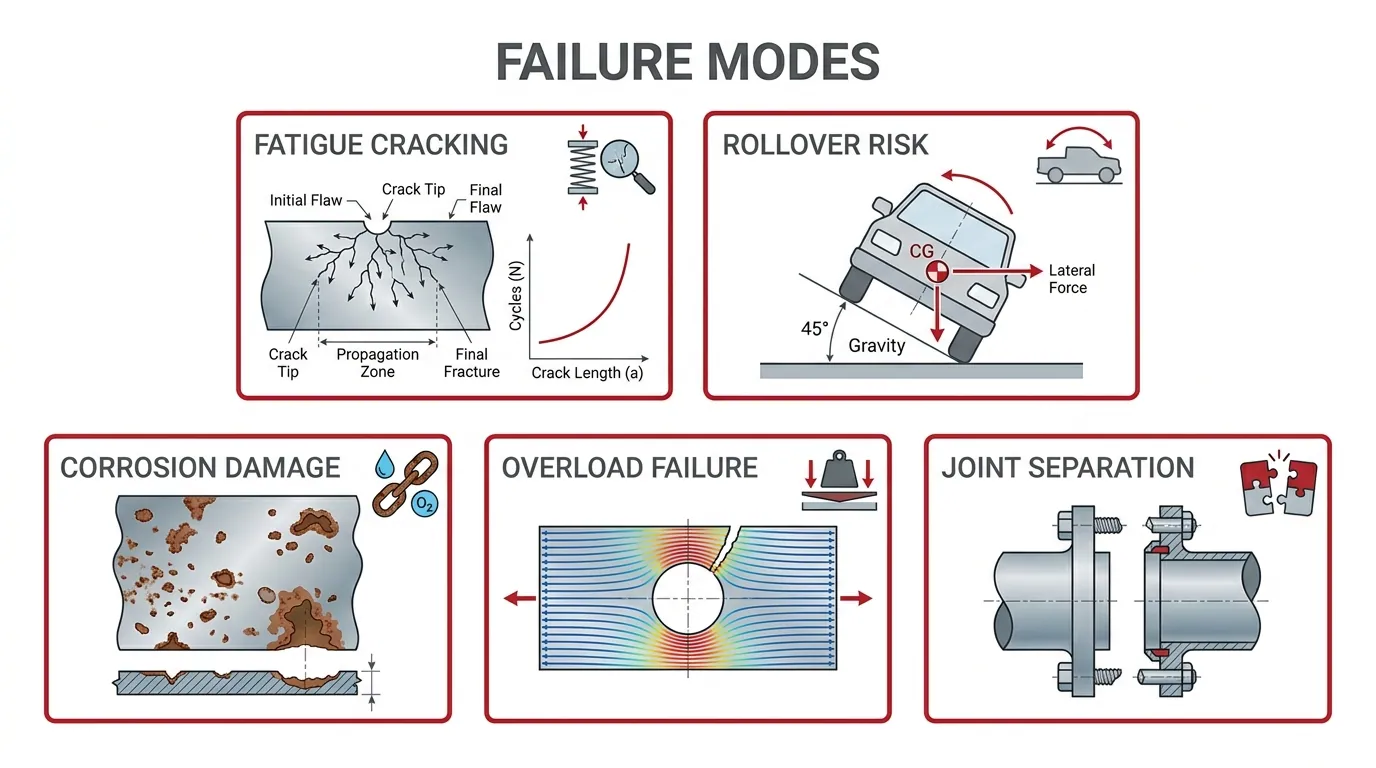
The common structural failure modes in high payload units include fatigue cracking, rollover from payload shift, corrosion-driven degradation, overload beyond ultimate limit state, and progressive failure at body-to-chassis interfaces. Each mode follows a distinct damage path that life-cycle inspection can detect before catastrophic loss.
Fatigue cracking is the most pervasive failure mode in heavy-duty trailers. When a structure endures repeated loading and unloading cycles, cracks initiate at stress concentrations and propagate until fracture occurs. As Pu Huang, Yunxiang Yin, Daniel McNaulty, and Wenyi Yan write in Engineering Failure Analysis (Monash University), “This phenomenon is known as fatigue and is one of the most common sources behind the failures of mechanical structures, including aircrafts, ships, etc. It is also commonly seen in many heavy-duty trailers.” Weld toes, gusset terminations, and abrupt section changes are the typical initiation sites because localized stress ranges at these details govern crack growth rate, not the base material’s bulk strength.
Rollover represents a high-consequence failure mode closely linked to center-of-gravity height and payload shift during transit. According to the National Transportation Safety Board, GES crash data for 1999 to 2004 indicated that an average of 1,265 cargo tank rollovers occurred annually, with approximately 702 (55.5 percent) involving a truck-tractor in combination with a cargo tank semitrailer. Liquid surge, uneven load distribution, and high-mounted equipment all raise the center of gravity and narrow the rollover stability margin.
Additional failure modes that compound these risks include:
- Corrosion-driven section loss. Wet-dry cycling and chloride exposure reduce wall thickness at chassis rails and subframe connections, weakening load paths over time.
- Overload beyond ultimate limit state. Exceeding GVWR or individual axle weight ratings causes yielding in load-carrying members that were not designed for the applied force.
- Progressive failure at body-to-chassis interfaces. When one mounting point loses capacity, adjacent connections absorb redistributed loads, accelerating sequential failures along the payload path.
- Floor system deflection and delamination. Concentrated point loads on improperly supported floor assemblies cause permanent deformation or composite layer separation.
Most of these failure modes share a common thread: they begin at discrete, inspectable locations rather than across entire structural members. That characteristic makes life-cycle inspection programs highly effective at catching damage before it cascades. In practice, the most dangerous failures are not sudden; they are progressive sequences that could have been interrupted at an earlier stage. Competitive guidance commonly underdevelops the distinction between these individual modes and their interaction, yet understanding that overlap is what separates a robust inspection protocol from a checkbox exercise.
Recognizing these failure modes early is essential; integrated design-to-fabrication workflows help embed the necessary inspection access and structural redundancy from the start.
How Does Vertical Integration Improve High Payload Unit Design?
Vertical integration improves high payload unit design by unifying design, fabrication, assembly, and testing under one roof, eliminating the interface gaps that compromise complex mobile structures. The sub-sections below explain how end-to-end custom fabrication addresses structural challenges and summarize the article’s key takeaways.
Can Craftsmen Industries’ End-to-End Custom Fabrication Solve Complex High Payload Structural Challenges?
Yes, Craftsmen Industries’ end-to-end custom fabrication can solve complex high payload structural challenges. By controlling every phase in-house, from initial engineering and material selection through welding, assembly, and quality verification, Craftsmen Industries maintains tight interface control across every load path and connection point.
This integrated product realization approach matters because non-commercial guidance rarely connects design, fabrication, testing, digital traceability, and lifecycle sustainment into a single workflow for high payload mobile platforms. When separate vendors handle different stages, misaligned tolerances and undocumented design decisions create weak points that surface only under real-world dynamic loads.
As the U.S. National Science Foundation notes, its Manufacturing Systems Integration Program emphasizes “the digital integration of design and manufacturing within the larger life cycle ecosystem.” Craftsmen Industries applies this principle operationally: design intent carries directly into fabrication without translation losses, supporting verification, reconfiguration, and long-term sustainment of every unit produced.
What Are the Key Takeaways About Structural Design for High Payload Mobile Units?
The key takeaways about structural design for high payload mobile units center on five actionable principles:
- Define the complete load envelope first. Every design decision, from material grade to joint detail, depends on accurately identifying static, dynamic, live, distributed, and point loads across all lifecycle phases.
- Match materials to the specific service environment. No single alloy or composite suits every application; steel, aluminum, FRP, and hybrid combinations each carry distinct trade-offs in strength-to-weight ratio, fatigue resistance, corrosion behavior, and repairability.
- Engineer weight distribution as a structural system. Center-of-gravity placement, axle load balancing, and cargo securement are not afterthoughts; they directly govern stability, regulatory compliance, and fatigue life.
- Qualify every joint and connection for its actual stress range. Fatigue strength depends on the real load path through each weld toe, bolt group, and subframe mount, not on bulk material properties alone.
- Integrate design and manufacturing under one workflow. Vertically integrated fabrication, as practiced by Craftsmen Industries, closes the gaps between engineering intent and built reality, reducing rework and containing lifecycle cost.
Authoritative sources do not establish universal values for material cost, axle-balancing tolerance, floor payload capacity, or subframe thickness across all high payload mobile units. Each project demands source-specific regulatory limits, validated test conditions, and service-environment analysis rather than generalized benchmarks.
Filter Posts by Tag
related posts

As the workplace continues to shift, so do the demands for luxury mobile office trailers that provide comfort, functionality, and cutting-edge technology.
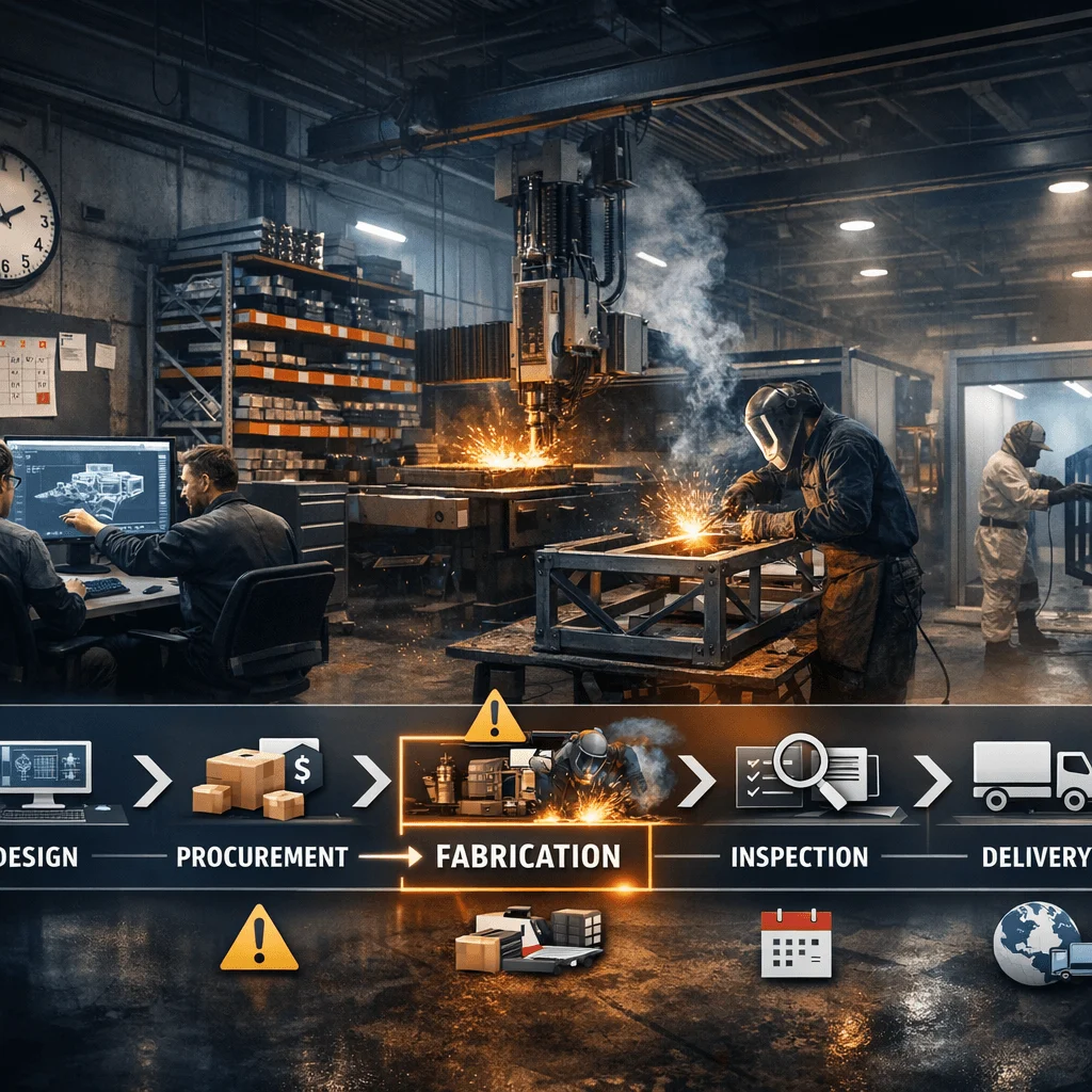
A custom fabrication lead time is the total duration between [...]

What are the needed qualifications for a career in industrial fabrication industry? The experts in this blog are pointing the requirements. Read on!
